04.07 Model Laser Cut Project in Fusion 360
Assignment Deliverables
- Fusion 360 .f3d model file
- Rendering(s) of project with appearances applied (.png or .jpg)
Assignment Overview
Using your sketches, cardboard model, and third angle projections, make a model of your laser cut stand in Fusion 360. Each piece of the project should be a separate component so later the parts can be layed flat for laser cutting.
You are required to use at least one user parameter dimension for “ply” or the thickness of the material you are cutting. Materials vary in width, so we will measure the material before cutting on the laser cutter. When we know the real thickness of the material using digital calipers , then we can change the “ply” variable and the model will produce an accurate cut file.
Model Stand in Fusion 360
If you prefer, you can import your third angle projection sketches to use as guides you start your first sketch. You need to calibrate the size of the sketch to be the correct scale in your Fusion 360 file. Then you can use the sketch as a guide to create your digital sketch. This step is not necessary but some may like it. This video shows how to import an image as a canvas in Fusion 360.
If you are making detailed organic forms or drawing an image to use as the contours of the sides or other parts of your stand it can be difficult to draw complex shapes and images in Fusion. You can draw you image or character in Illustrator and export it as an SVG or DXF. Then you can import that file into Fusion 360. Once in fusion the file acts as a sketch and you can extrude it right away to be a piece of your model. This workflow is better than drawing a complex organic form in Fusion.
Keep Parts as Separate Components
Make a new component at the top level of you model for each part. The top level should be the “parent” of each of the other components. The components should be at the same outline level in the browser and not nested inside each other.
Design Considerations
Think about how your pieces will hold together. Add tabs and holes and any other design features needed to attach the different pieces. You can use the “Combine” modify action to cut out pieces using other pieces as “tools”.
- Will you use pinned finger joints?
- Will you use glue?
- Will you use tabs and holes?
- Will you have bendable living hinges?
- Will you use snap clips?
- Will you use captive nut joints?
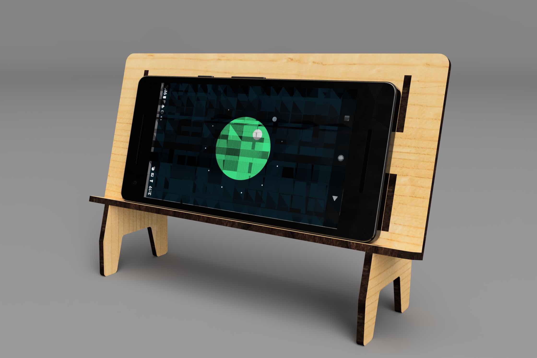
Add Appearances and Export Render
In Fusion 360 add appearances to you model as you wish and export a render. Label the file YYYYMMDD Lastname Firstname Laser Cut Stand Render.png/jpg
Make the model look the way you want the final product to look. If you are going to paint pieces then paint the pieces in the render. If you will have etchings then put an image decal on to represent the etchings.
Make sure your render image is well composed and high resolution with at least one direction 4000px. Choose a 4:3 16:9 or 1:1 aspect ratio. You can make multiple render views.
Example of each part of the stand as a separate component at the top level assembly in Fusion 360.
Grading Rubric
| Assessment | Weight |
|---|---|
| Design of Stand | 30 points |
| Use “ply” user parameter | 20 points |
| Use Separate Components for Pieces | 30 points |
| Use of Joints to Connect Parts | 30 points |
| Render Image Composition | 20 points |
| Materials Applied | 10 points |
| Render Aspect Ratio not set to Viewport | 10 points |
| File Management | 10 points |